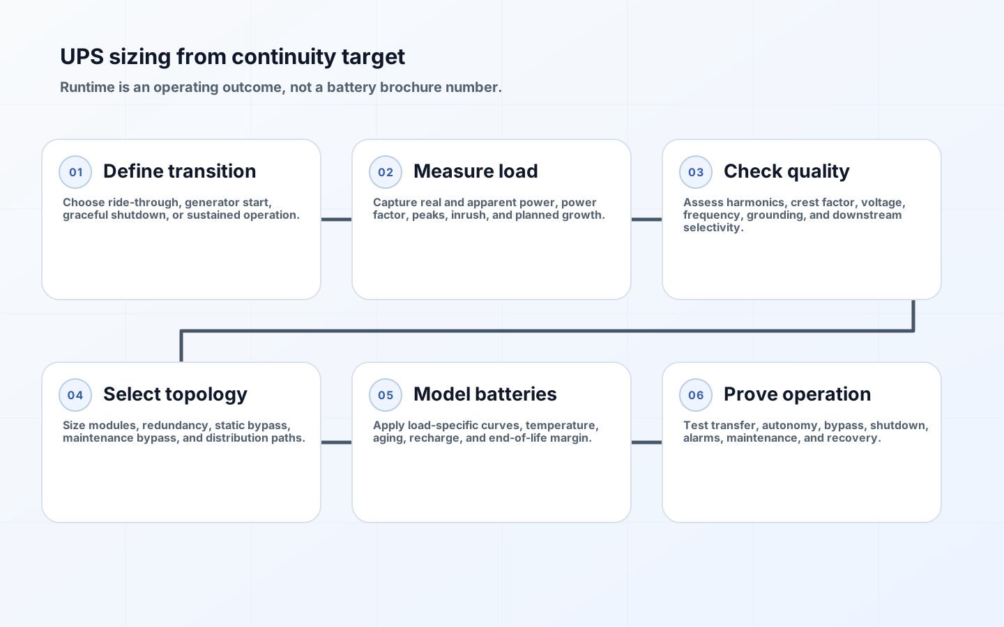
UPS sizing for a server room begins with the business transition that must survive a utility disturbance. Some rooms need only enough ride-through for a generator to start and stabilize. Others need time for an orderly application and storage shutdown, or continued operation through a defined outage. Selecting a kVA number first reverses the decision: it can buy excess converter capacity while still failing to provide the required battery runtime at the actual load.
A defensible design connects measured load, power quality, topology, redundancy, battery technology, environmental conditions, maintenance bypass, generator behavior, and growth. It also distinguishes a product estimate from a tested operating outcome. IEC 62040-3 defines UPS performance and test requirements, while installation, wiring, fire protection, and worker safety remain subject to applicable codes, authorities, and manufacturer instructions. Qualified electrical professionals must own the final design and testing plan.
Translate continuity objectives into a runtime requirement
Write the outage sequence in minutes and actions. Include disturbance detection, UPS transfer, generator start attempts, warm-up and stabilization, automatic transfer, application decision points, graceful shutdown duration, and a reserve for variance. If no generator exists, define the longest outage the business will ride through and what happens when that time expires. Runtime must cover the worst credible transition, not the average utility interruption. Decide which loads remain protected and which can be shed automatically.
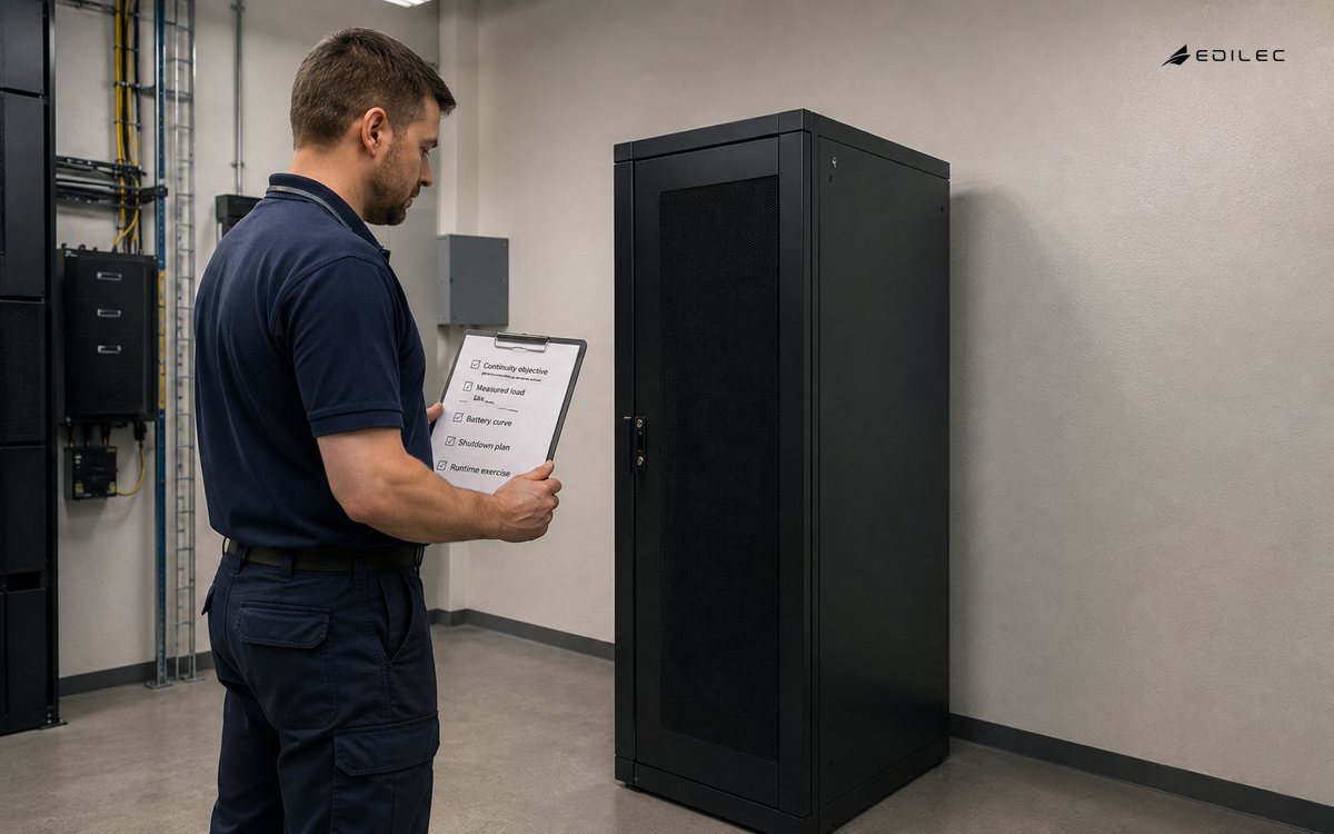
Classify loads by consequence and shutdown dependency. Network, identity, storage, virtualization control, monitoring, security, and cooling controls may be necessary to shut compute down safely. A printer or comfort-cooling circuit may not be. Document restart order and utility restoration behavior because a room can overload the UPS or generator when devices restart together. Where continuity depends on a generator, coordinate fuel, maintenance, starting batteries, test frequency, transfer switches, grounding, and the UPS input tolerance.
| Continuity target | Runtime basis | Required coordination | Acceptance evidence |
|---|---|---|---|
| Power-quality ride-through | Longest switching or disturbance interval plus margin | UPS transfer and sensitive load compatibility | No load reset during qualified events |
| Generator bridge | Start attempts, stabilization, and transfer time plus reserve | Generator frequency/voltage behavior and ATS sequence | Repeated cold-start transfer under representative load |
| Graceful shutdown | Detection, decision delay, application quiesce, storage flush, and shutdown | Orchestrated dependency order and restart plan | All critical systems stop cleanly before autonomy limit |
| Short-outage operation | Business-approved outage duration | Load shedding and user communication | Protected service remains within objectives |
| Maintenance continuity | Time or topology needed during module/battery service | Maintenance bypass and redundant path | Approved service procedure without unintended interruption |
Measure load and power quality at the intended boundary
Measure real power in kW, apparent power in kVA, power factor, phase currents, voltage, frequency, peaks, and variation across representative operating cycles. Include cooling or ventilation only if it is genuinely on the protected output. Inventory every downstream device, but do not size solely by adding nameplates. Nameplates bound equipment input; a qualified measurement campaign reveals the operating profile. Reconcile both and explain the chosen design load, measurement uncertainty, and planned additions.
UPS output and battery demand are affected by non-linear loads, harmonics, crest factor, inrush, step changes, and power factor. Modern server power supplies can have good power-factor correction, yet the complete room still needs verification. Check whether downstream transformers, static transfer switches, and protective devices tolerate the waveform and available fault current. Confirm selective coordination so a downstream fault clears locally instead of dropping the entire UPS output. These calculations require project-specific electrical engineering.
Choose an operating point that respects the UPS efficiency curve and leaves deliberate growth capacity. Very low loading can waste conversion energy and make modular capacity uneconomic; very high loading can eliminate redundancy and limit step-load response. ENERGY STAR recommends right-sizing and efficient operating modes, but efficiency cannot supersede continuity and power-quality needs. Record whether growth will be met by reserved module slots, another frame, distribution work, or load migration, with a lead time for each.
Select topology, bypass, and redundancy as one system
Compare standby, line-interactive, and double-conversion behavior against load sensitivity, disturbance environment, efficiency, maintainability, and budget. For a material server room, the question extends beyond topology to static bypass, manual maintenance bypass, input and output switchgear, parallel modules, synchronization, monitoring, and service access. A bypass path may expose the load to utility quality or create a different fault boundary. Document every operating mode and the conditions that enter it.
Define redundancy mathematically. In an N+1 modular system, the remaining N modules must support the full design load when one module is unavailable, including the intended growth state. Batteries, bypass, controls, distribution, cooling, and upstream supply may still be single points of failure. A dual-bus design can improve isolation only when load power supplies are correctly split and single-corded devices use suitable transfer arrangements. Test the actual path mapping; labels on two cabinets do not prove independence.
| Factor | Why it matters | Conservative treatment | Verification |
|---|---|---|---|
| Load level | Battery discharge is not a linear kWh division | Use manufacturer curve for the specified configuration and load | Witnessed discharge or accepted capacity test |
| Temperature | Changes battery life, performance, and safety controls | Use approved operating range and environmental monitoring | Trend room and battery temperatures |
| Aging | End-of-life capacity is lower than new-battery capacity | Apply approved aging and replacement criterion | Periodic health and capacity evidence |
| Conversion losses | Battery must supply UPS losses as well as output | Use tested efficiency at the operating point | Input/output metering during test |
| Cell/module failure | A weak unit can limit a string or cabinet | Design monitoring, isolation, redundancy, and replacement | Alarm and maintenance exercise |
| Recharge requirement | Repeated events may occur before full recharge | Model charger capacity and generator loading | Timed recharge under operating conditions |
Size battery autonomy from load-specific curves and end-of-life needs
Do not calculate runtime by dividing nominal battery watt-hours by server watts. Discharge rate, cutoff voltage, battery chemistry, cell arrangement, temperature, age, UPS losses, and control limits shape usable autonomy. Use manufacturer performance data for the exact UPS, battery cabinet, string count, and load. Define whether the requirement applies at beginning of life or at the replacement threshold; continuity plans usually need the latter, with margin for measurement and environmental variation.
Compare valve-regulated lead-acid, lithium-ion, and other supported storage on service life, footprint, weight, temperature sensitivity, monitoring, recharge, fault containment, transport, disposal, availability, and local code implications. IEC 62040-1 addresses UPS safety, while battery-specific standards and local requirements may also apply. The cheapest initial cabinet can be costly if replacements require frequent outages. Conversely, a long-life technology has little value without trained service, compatible fire strategy, and available parts.
Commission autonomy and maintain the complete continuity chain
Commission alarms, communications, transfer, bypass, load steps, generator interaction, runtime, shutdown signals, emergency power-off interfaces where applicable, and restoration. Use a safe method approved by the electrical engineer, facility owner, and manufacturer. A load bank can test the UPS independently; a controlled integrated test proves the real downstream sequence. Record test load, battery condition, temperatures, timestamps, waveforms, alarms, and deviations so future tests are comparable.
Operate a maintenance schedule for visual inspection, torque or connection checks as specified, filters and fans, firmware, capacitors, batteries, sensors, bypass mechanisms, generator coordination, and alarm routing. Trend load and autonomy margin as equipment changes. Re-run the shutdown timing when applications or storage architecture changes. Maintain a current one-line diagram, protected-load inventory, spare strategy, emergency contacts, and change procedure. The UPS is one element of continuity; an untested shutdown script or blocked cooling path can consume its entire benefit.
Key takeaways
- Define the transition or shutdown outcome first, then derive minutes of required autonomy.
- Measure kW, kVA, power factor, phase current, peaks, and power-quality characteristics at the intended boundary.
- Size N+1 against the surviving configuration and inspect bypass, batteries, controls, cooling, and distribution for shared failures.
- Use exact load-specific battery curves with temperature, aging, UPS losses, recharge, and end-of-life criteria.
- Commission the integrated chain and keep runtime evidence current as loads, software, and facilities change.
FAQ
Should a UPS be sized in kW or kVA?
Check both. The UPS has real-power and apparent-power limits, and the load power factor determines their relationship. Also verify phase current, crest factor, harmonics, and step response. The binding limit depends on the actual UPS and load.
How much UPS growth margin is appropriate?
Derive it from an approved workload forecast, uncertainty, redundancy state, and expansion lead time rather than a universal percentage. Modular expansion can reduce initial oversizing, but only if frame, battery, switchgear, and distribution capacity are reserved.
Is the UPS runtime display enough evidence?
It is useful telemetry, not complete acceptance evidence. Its estimate depends on configured battery data and current conditions. Periodic controlled tests, battery health records, and verified shutdown or generator sequences establish whether the continuity objective is still achievable.
Conclusion
A well-sized UPS is a tested bridge between a power event and a defined operational outcome. Measured load determines converter capacity, the continuity sequence determines autonomy, failed-state analysis determines redundancy, and battery curves determine usable runtime. When bypass, generator, shutdown, maintenance, and restoration are commissioned together, the server room gains a continuity system rather than an expensive battery estimate.