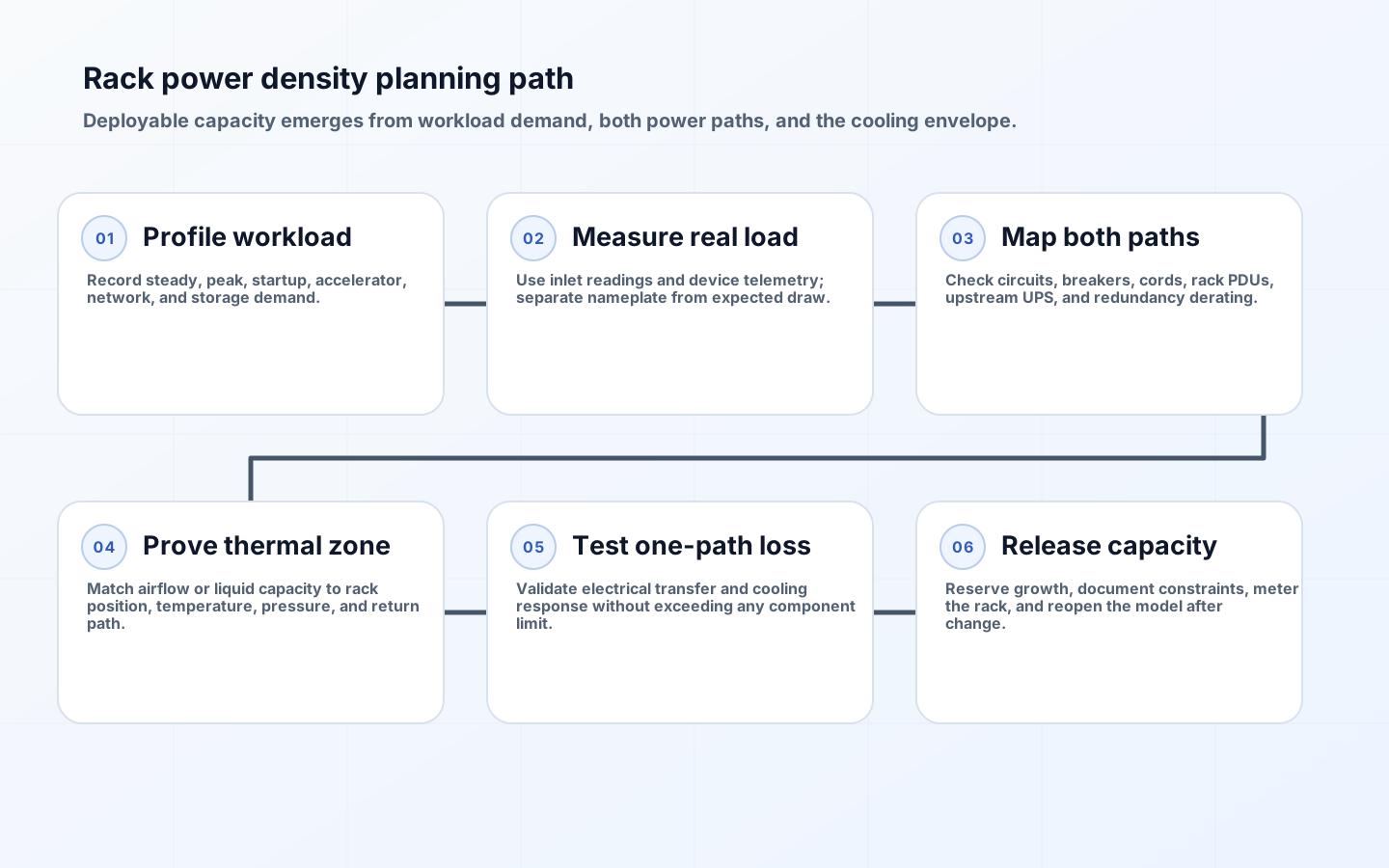
Rack power density planning is the work of proving that a workload can be powered and cooled in a specific position under normal operation, foreseeable peaks, and component failure. A target such as 40 kW per rack is useful for portfolio planning, but it is not permission to install 40 kW of equipment. The deployable limit may instead be set by a branch circuit, one side of an A/B feed, a rack PDU connector, an upstream UPS module, local airflow, a coolant loop, floor loading, or the time available to add capacity.
Modern accelerator clusters make those constraints more coupled. Dense nodes can change electrical demand quickly, reject concentrated heat, require substantial network equipment, and occupy fewer rack units than the supporting power and cooling equipment suggests. The planning objective is therefore an auditable envelope: expected IT load, permitted peak, residual capacity on every required path, thermal removal capability, failed-state behavior, and an owner for the remaining reserve.
Build a rack capacity envelope from workload evidence
Begin with the workload rather than the server nameplate. Record node count, CPU and accelerator power modes, memory, local storage, top-of-rack switching, management devices, and any in-rack cooling equipment. Capture steady demand, synchronized compute peaks, boot and firmware-update behavior, and the planned growth step. Nameplate values protect product and circuit design; they often overstate ordinary draw, yet an average reading can understate the burst that trips a protective device. Use both as bounds and replace assumptions with metered evidence during qualification.
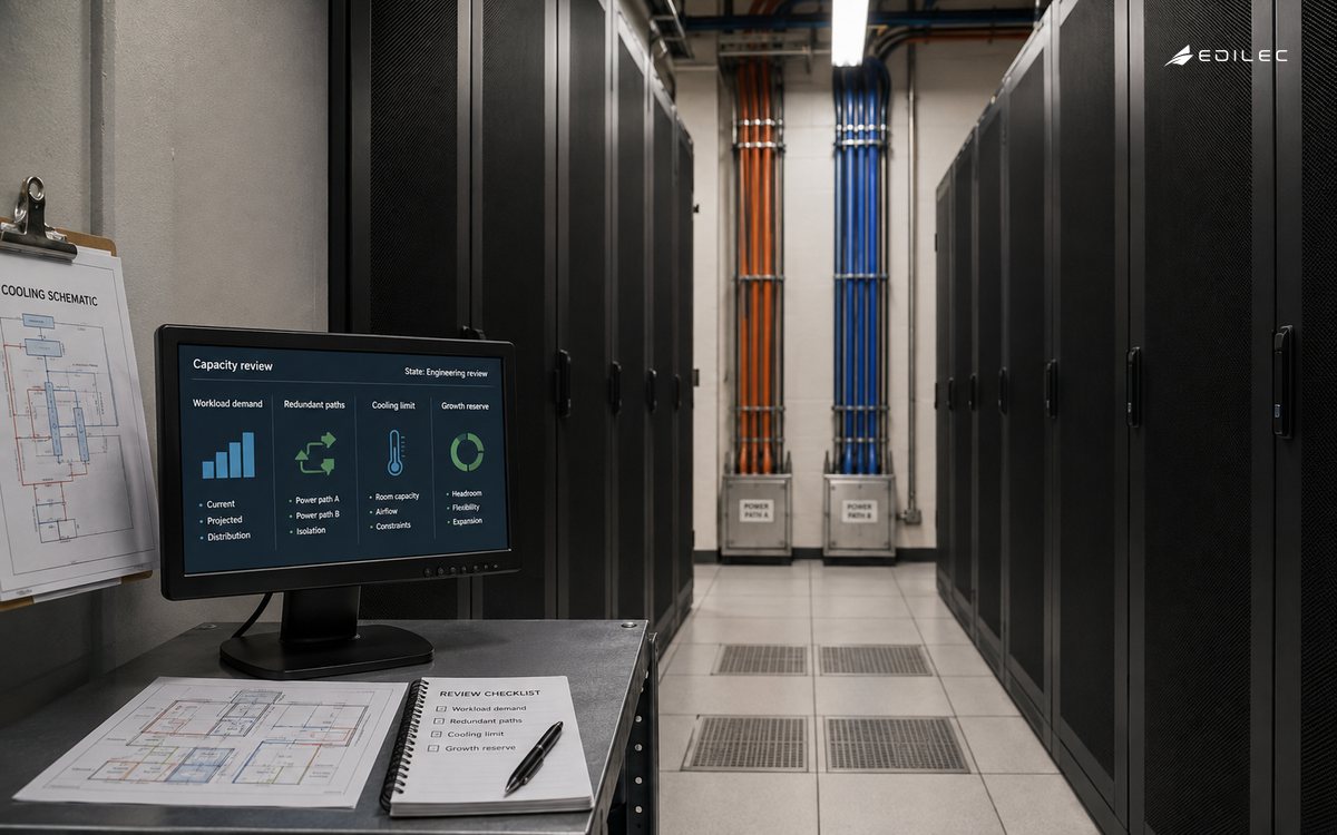
Express capacity at several levels: rack IT kW, apparent power in kVA where power factor matters, current per phase, rack-unit occupancy, heat rejected to air, heat transferred to liquid, coolant flow, and weight. State the ambient and supply conditions under which the envelope is valid. A cooling claim without inlet temperature or water temperature is incomplete, just as an electrical claim without voltage, phase arrangement, and redundancy mode is incomplete. Version the envelope when firmware power limits, node populations, or operating profiles change.
| Input | Evidence | Planning use | Common mistake |
|---|---|---|---|
| IT demand | Metered node and switch load across representative jobs | Set expected and peak kW | Using one idle sample |
| Electrical path | Breaker, conductor, receptacle, PDU, phase, UPS, and generator data | Find the lowest safe path limit | Counting A and B twice during redundancy |
| Thermal path | Airflow, inlet and return temperature, liquid flow, supply temperature, and heat split | Prove heat removal at the location | Using room-average temperature |
| Physical limits | Rack, floor, cable, manifold, and service-clearance ratings | Confirm installability and maintenance | Treating free rack units as capacity |
| Growth reserve | Approved expansion scenario and lead time | Protect the next planned change | Holding unowned headroom forever |
Trace every electrical path and derate for redundancy
Draw the path from utility or generator through switchgear, UPS, distribution, branch circuit, receptacle, rack PDU, cord, and equipment power supply. Record continuous-load policy, applicable electrical code, manufacturer limits, breaker trip curves, conductor ratings, connector ratings, and phase balance. The rack limit is the lowest applicable constraint, not the sum of convenient labels. Facilities engineering must approve the calculation because installation rules and protective-device coordination depend on jurisdiction and the actual distribution design.
For dual-corded equipment, calculate normal and failed states. If A and B each carry roughly half the load during normal operation, either side may need to carry the full surviving load when the other is unavailable. Do not place a rack at 80 percent of each path and call it redundant if transfer would push the surviving side beyond policy or trip limits. Include single-corded devices and automatic transfer switches explicitly. At room scale, check whether many racks transfer simultaneously onto the same UPS, PDU, or generator path.
Balance three-phase loads at the device population actually planned. Small imbalances repeated across many racks can consume neutral capacity and strand a phase even when total kW appears available. Intelligent rack PDUs provide useful branch and outlet observations, but meter accuracy, sampling interval, alarm thresholds, and data retention must be documented. Set warning thresholds below the action boundary so capacity teams have time to respond rather than receiving the first meaningful signal at a breaker trip.
Prove cooling at the rack location, not at room average
Air-cooled capacity depends on delivering sufficient conditioned air to equipment inlets and returning heated air without recirculation. Model containment, tile or duct delivery, fan curves, pressure, blanking panels, cable obstruction, neighboring racks, and the loss of a cooling unit. Instrument top, middle, and bottom inlets because a safe room average can conceal a hot upper server. ASHRAE environmental guidance is a starting boundary; equipment warranty ranges, reliability objectives, and the facility control strategy determine the operating band.
For liquid-assisted racks, split the heat budget between liquid and residual air. Direct-to-chip cooling removes major component heat but fans, memory, storage, power supplies, and networking can still load the air system. Specify coolant supply temperature, allowable return, flow and pressure range, CDU duty, facility-water interface, and behavior during pump or controls failure. A rack should not be released merely because a manifold exists nearby; the connected loop must have hydraulic and heat-rejection capacity under the intended redundancy state.
| Observed constraint | Possible response | Tradeoff to validate | Release evidence |
|---|---|---|---|
| Branch circuit limit | Add circuits or lower server power caps | Construction time versus reduced compute throughput | Load test below approved alarm threshold |
| A/B failed-state overload | Reduce rack population or redesign feeds | More racks and network cabling versus true redundancy | One-path simulation with surviving path in bounds |
| Airflow shortfall | Improve containment, redistribute racks, or adopt liquid capture | Facility work and operating complexity | Inlet temperatures stable at representative load |
| Cooling-loop shortage | Add CDU or loop capacity, or phase deployment | Capital lead time and redundancy interaction | Flow, temperature, pressure, and failure test |
| Floor or rack weight | Use approved rack/position or split equipment | Longer fabric links and space consumption | Structural and installation approval |
Use diversity and reserve without inventing capacity
Portfolio plans often apply diversity because not every rack reaches maximum draw at once. That may be reasonable for upstream utility and cooling economics, but it must be supported by workload scheduling, telemetry, and a stated coincidence assumption. Accelerator fleets running the same training window can be highly correlated. Capacity that exists only because teams promise not to peak together requires an enforceable scheduler or power-control policy; a spreadsheet assumption is not a control.
Separate safety margin, reliability headroom, measurement uncertainty, and planned growth. Combining them into one percentage makes reserve easy to consume without understanding the consequence. Assign each reserve an owner and release rule. For example, uncertainty reserve can shrink after a representative burn-in, while N+1 headroom must remain available. Model construction lead time as part of capacity: ten spare kilowatts that take eighteen months to replenish may be more valuable than a larger amount that can be added next week.
Commission the rack and keep the model alive
Commission with the intended equipment population and a representative high-load job. Verify phase currents, rack PDU alarms, power-supply redundancy, inlet temperatures, return temperatures, coolant values, fan behavior, controls, telemetry, and labeling. Exercise the permitted failure scenarios with change control: loss of one feed, transfer to bypass where relevant, failed fan or pump response, and restoration. Do not improvise electrical failure tests; qualified facilities personnel must define and supervise them.
After release, trend peak and percentile loads rather than only monthly energy. Alert on capacity erosion, phase imbalance, repeated transfers, abnormal inlet temperatures, coolant drift, and changes in heat split. Tie equipment moves and firmware power-policy changes to capacity review. A rack record should show installed assets, approved envelope, current readings, open exceptions, upstream dependencies, and next expansion date. Periodically reconcile the logical inventory with physical inspection because undocumented moves invalidate otherwise precise calculations.
Key takeaways
- Treat kW per rack as a planning label until the complete electrical, thermal, and physical path is proven.
- Calculate A/B feeds for the surviving-path load and check shared upstream failure domains.
- Measure representative steady, peak, and transition behavior; retain nameplate as a boundary, not a forecast.
- Separate liquid-captured heat from residual air load and commission both cooling paths.
- Name every reserve and reopen the envelope after equipment, firmware, workload, or facility change.
FAQ
Should rack capacity use average or peak power?
Use both for different decisions. Energy and some upstream planning can use a justified demand profile, while branch circuits, rack PDUs, transfer states, and thermal control need peak and transient evidence. Define the sampling interval because a five-minute average can hide a protective-device-relevant burst.
Can server nameplate power be added to size the rack?
It provides a conservative bound but rarely a good operating forecast. Qualify representative configurations under real work, include network and cooling auxiliaries, and preserve enough margin for uncertainty and abnormal modes. Applicable code and manufacturer instructions still govern the final design.
Why can a data center have empty racks but no capacity?
Space, power, cooling, weight, and network capacity are separate resources. A vacant rack may sit in a thermal zone or electrical path that cannot accept the requested load. Capacity reporting should show all binding resources instead of reporting rack units alone.
Conclusion
Reliable rack power density planning converts an attractive density target into a location-specific operating contract. Workload evidence establishes demand; path analysis establishes electrical limits; thermal commissioning proves heat removal; and failed-state tests establish whether redundancy is real. When the resulting envelope is metered, owned, and revised after change, high-density compute can grow without turning nominal rack space into hidden operational risk.