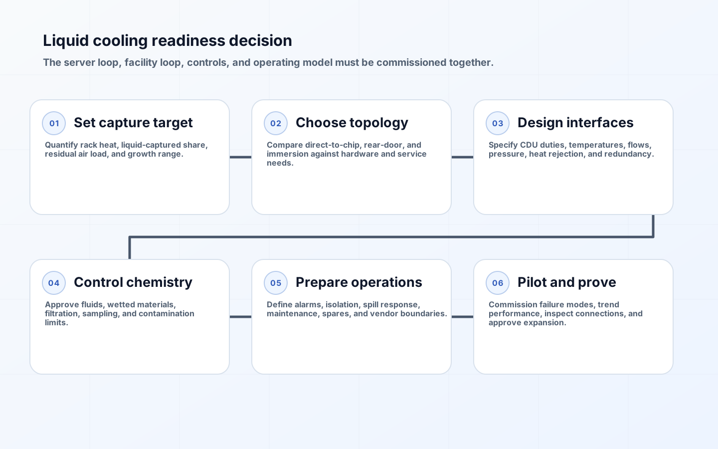
Data center liquid cooling readiness is not a yes-or-no property of a building. It is a matched design across IT equipment, rack manifolds, coolant distribution units, facility-water systems, heat rejection, controls, water or fluid quality, and the people who operate them. A facility can have chilled water nearby yet remain unready because temperatures, pressures, materials, redundancy, monitoring, or maintenance access do not match the selected technology.
The commercial decision should begin before server procurement. Direct-to-chip cold plates, rear-door heat exchangers, and immersion systems place different requirements on servers, racks, fluids, piping, service methods, warranties, and residual air cooling. The right choice follows a measured heat load and an operating model. It cannot be inferred from rack density alone, and a vendor demonstration does not prove that the facility can support a fleet through leaks, contamination, component replacement, and loss of a cooling path.
Define the heat-capture boundary before choosing technology
Create a heat balance for the proposed rack. Identify total IT power, the portion expected to reach liquid, the portion remaining in air, heat from network switches and power equipment, and the variability across workloads. A direct-to-chip design may capture processors and accelerators while memory, drives, voltage regulators, and power supplies continue to heat the air. The room air system must retain enough capacity and distribution quality for that residual load, including startup and degraded liquid operation.
Specify the design range rather than one peak number: initial population, expected expansion, normal workload, power-capped mode, maximum qualified mode, and an abnormal state. State equipment inlet limits and facility supply conditions. ASHRAE’s current AI data-center framework emphasizes integrated design because electrical and thermal choices now interact at rack scale. A warmer facility-water supply can improve heat-rejection economics, for example, but only if cold plates, CDUs, controls, and weather extremes can meet component temperature limits.
| Approach | Primary heat path | Facility and rack implications | Operational tradeoff |
|---|---|---|---|
| Direct-to-chip cold plate | Coolant contacts plates on high-heat components | CDU, manifolds, quick disconnects, residual air cooling | Familiar server access, but many fluid connections and partial heat capture |
| Rear-door heat exchanger | Server exhaust transfers heat at rack rear | Door weight, water connection, airflow compatibility, condensate control where applicable | Less server modification, but door and aisle service constraints |
| Single-phase immersion | Equipment is submerged in dielectric fluid | Tanks, lifting, fluid handling, component qualification, floor planning | High heat capture, substantially different maintenance workflow |
| Two-phase immersion | Boiling fluid carries heat to condenser | Closed vessel, fluid containment, pressure and material controls | Efficient heat transfer with specialized fluid and service requirements |
| Hybrid deployment | Different zones or components use different paths | Parallel air and liquid capacity, clear operating boundaries | Incremental adoption, but more interfaces to monitor and support |
Design the facility and technology cooling loops as an interface
Document loop boundaries. A technology cooling system typically serves IT-side components and is separated through a CDU or heat exchanger from the facility-water system. For each side, specify supply and return temperature ranges, design flow, differential pressure, allowable ramp rates, filtration, expansion, fill and drain points, isolation, instrumentation, and pressure relief. Define who supplies the CDU, pumps, controls, manifolds, hoses, and couplings, and who owns performance when values at one boundary cause alarms at another.
Size for both duty and fault conditions. Consider pump or CDU module loss, a blocked filter, control-network failure, loss of facility water, loss of power, and the thermal inertia available before equipment throttles or shuts down. Redundancy labels are insufficient if redundant units share power, controls, piping, or an upstream heat exchanger. Decide whether workloads should power-cap, migrate, checkpoint, or stop on cooling degradation, then connect those states to telemetry and orchestration. Safe shutdown time is a design input.
Condensation risk depends on surface temperature and local dew point, not simply on using liquid. Establish a supply-temperature policy, dew-point sensing, alarm margin, and control response where surfaces could fall below ambient dew point. Review pipe routing, drip management, penetrations, seismic or movement allowances, and service clearance. Structural teams must assess filled rack, door, tank, and piping loads. Treat temporary hoses and commissioning equipment as part of the installation plan rather than an afterthought.
Control fluids, wetted materials, and connection quality
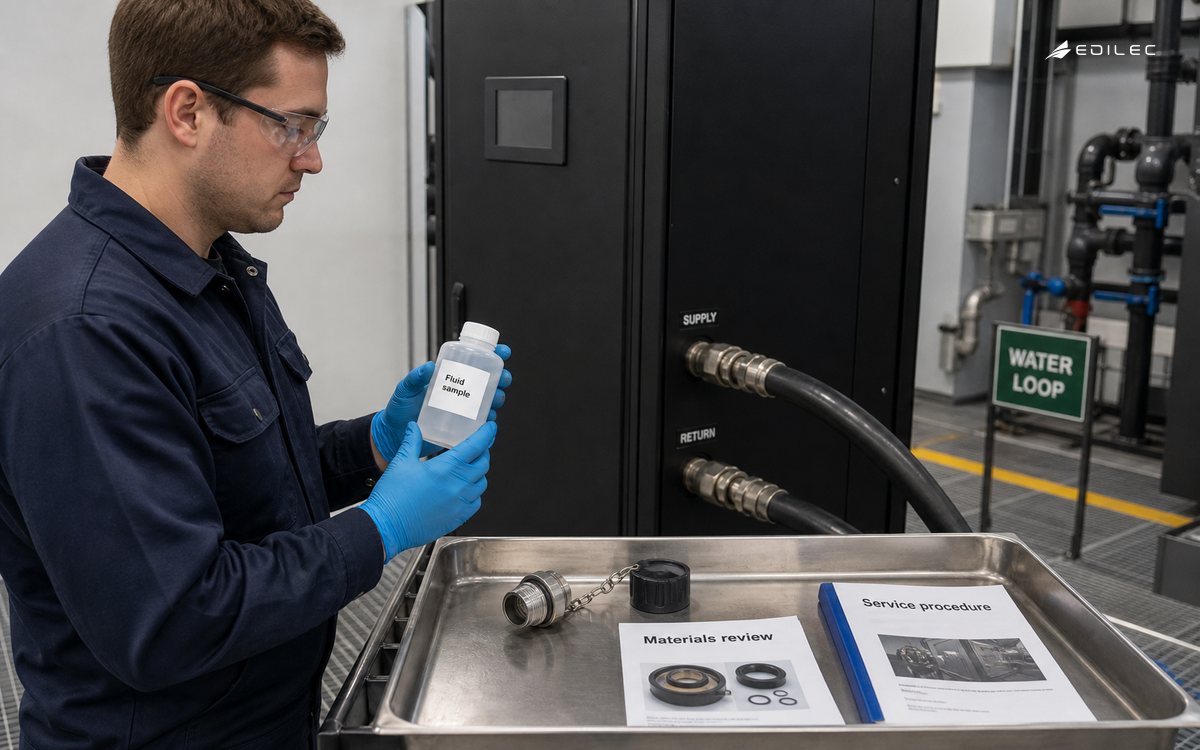
The fluid specification is a lifecycle contract. Define base fluid, additives, corrosion inhibitors, conductivity or resistivity where relevant, pH, biological control, particulate limits, dissolved metals, sampling points, test method, acceptance range, and corrective action. Water quality that is acceptable for a building loop may be unsuitable for fine cold-plate passages. Mixing approved fluids or topping up with untreated water can change chemistry. Maintain batch records and prohibit substitutions without compatibility review.
Create a wetted-material inventory across cold plates, seals, hoses, couplings, manifolds, pumps, heat exchangers, tanks, and test equipment. Obtain vendor compatibility statements for the intended temperature and service life. OCP’s advanced-cooling work explicitly addresses cold-plate loop requirements, fluids, and interoperable quick disconnects, illustrating why the interface needs more than a nominal pipe size. Qualify coupling insertion force, sealing, drip performance, cleanliness, labeling, and replacement cycles under the real rack arrangement.
| Control area | Evidence before pilot | Commissioning check | Operating record |
|---|---|---|---|
| Thermal performance | Heat balance and qualified temperature/flow envelope | Representative load and degraded-path test | Supply, return, flow, pressure, component temperature |
| Fluid quality | Approved specification and material compatibility matrix | Baseline sample after flush and fill | Scheduled samples, additions, corrective actions |
| Leak management | Detection zones, isolation design, spill plan | Sensor, alarm, valve, drain, and escalation tests | Alarm history, inspections, coupling changes |
| Serviceability | Approved procedures, tools, PPE, lifting and access plan | Observed component replacement | Training, permits, parts, procedure revisions |
| Accountability | Interface control document and warranty boundaries | Joint acceptance with named owners | SLA, defect ownership, change and incident records |
Prepare operations for leaks, maintenance, and mixed estates
Leak response should be specific to location and consequence. Zone sensors so operators can identify a rack, manifold, CDU, or pipe segment; define alarm severity; and automate only actions whose side effects are understood. Closing a valve may protect a room while rapidly removing cooling from running accelerators. The response runbook must coordinate facilities, IT operations, security, environmental health and safety, and the vendor. Include containment materials, isolation points, safe electrical approach, cleanup, fluid disposal, evidence capture, and authority to restore service.
Service work changes. Technicians may need fluid training, PPE, torque-controlled connections, caps and plugs, clean tools, sampling procedures, and lifting equipment. Decide whether a server can be hot-swapped, drained in place, moved to a service area, or exchanged as a sealed unit. Define the acceptable drip quantity and inspection. During a mixed air/liquid transition, label rack and server compatibility unmistakably and prevent an air-only replacement from entering a liquid-dependent slot or vice versa.
Pilot, commission, and scale with exit criteria
A useful pilot represents production density, piping distance, facility temperatures, workload variability, controls, and maintenance actions. Bench success at a vendor site does not test the building interface. Instrument energy, heat captured to liquid, residual air load, temperatures, flow, pressure, pump power, water use where applicable, alarms, throttling, connection events, fluid quality, and technician time. Run long enough to observe fouling trends and operational handoffs, not only a short performance benchmark.
Commission normal load, peak load, startup, planned shutdown, loss of a pump or CDU module, sensor failure, facility-water degradation, leak detection, valve operation, alarm routing, workload response, and restoration. Set pass criteria and a rollback disposition before the test. Expansion approval should cover a repeatable rack design, installation quality checks, spare strategy, training capacity, telemetry integration, and facility headroom. Scale in bounded zones so an early design correction does not require rebuilding the whole estate.
Key takeaways
- Start with a heat balance and residual air load; liquid cooling does not automatically remove every watt from the room.
- Treat the CDU boundary as a controlled interface with temperatures, flows, pressures, chemistry, redundancy, and owners.
- Approve fluids and all wetted materials as one compatibility system, with sampling and substitution control.
- Design leak response and equipment service before procurement because both shape rack, piping, training, and warranty choices.
- Scale only after representative-site commissioning proves normal, failed, maintenance, and restoration states.
FAQ
Is liquid cooling always more efficient than air cooling?
No. It can reduce fan and refrigeration work and enable warmer heat rejection, but total performance depends on pumps, CDUs, facility temperatures, residual air cooling, climate, load, and control. Compare measured whole-system energy and water outcomes at the required reliability level.
Does an existing chilled-water loop make a facility ready?
Not by itself. Verify temperature, flow, pressure, water quality, redundancy, connection locations, controls, heat-rejection capacity, and ownership against the technology loop. A CDU may isolate loops, but it cannot correct every upstream capacity or resilience gap.
Can a design be called leak-free?
Use qualified components and installation controls to reduce probability and consequence, but plan for detectable leakage and maintenance error. Specify detection, isolation, safe workload response, cleanup, evidence, and restoration rather than relying on an absolute claim.
Conclusion
Liquid cooling readiness is an operating capability, not a pipe at the edge of a rack. The facility becomes ready when the selected heat-capture method fits the IT equipment, loops have a governed interface, fluids and materials stay within specification, technicians can service the system, and failure responses protect both people and workloads. A representative pilot turns those agreements into evidence and creates a repeatable basis for high-density expansion.